Categories
Blogs

COMMISSIONING & EFFICIENT OPERATION

TOPICS COVERED :

Stages of commissioning

  1.  Pre-start checks
  2.  Efficiency calculation
  3. Tips on efficient operation   
  4. Emergencies & troubleshooting
efficient commissioning operation

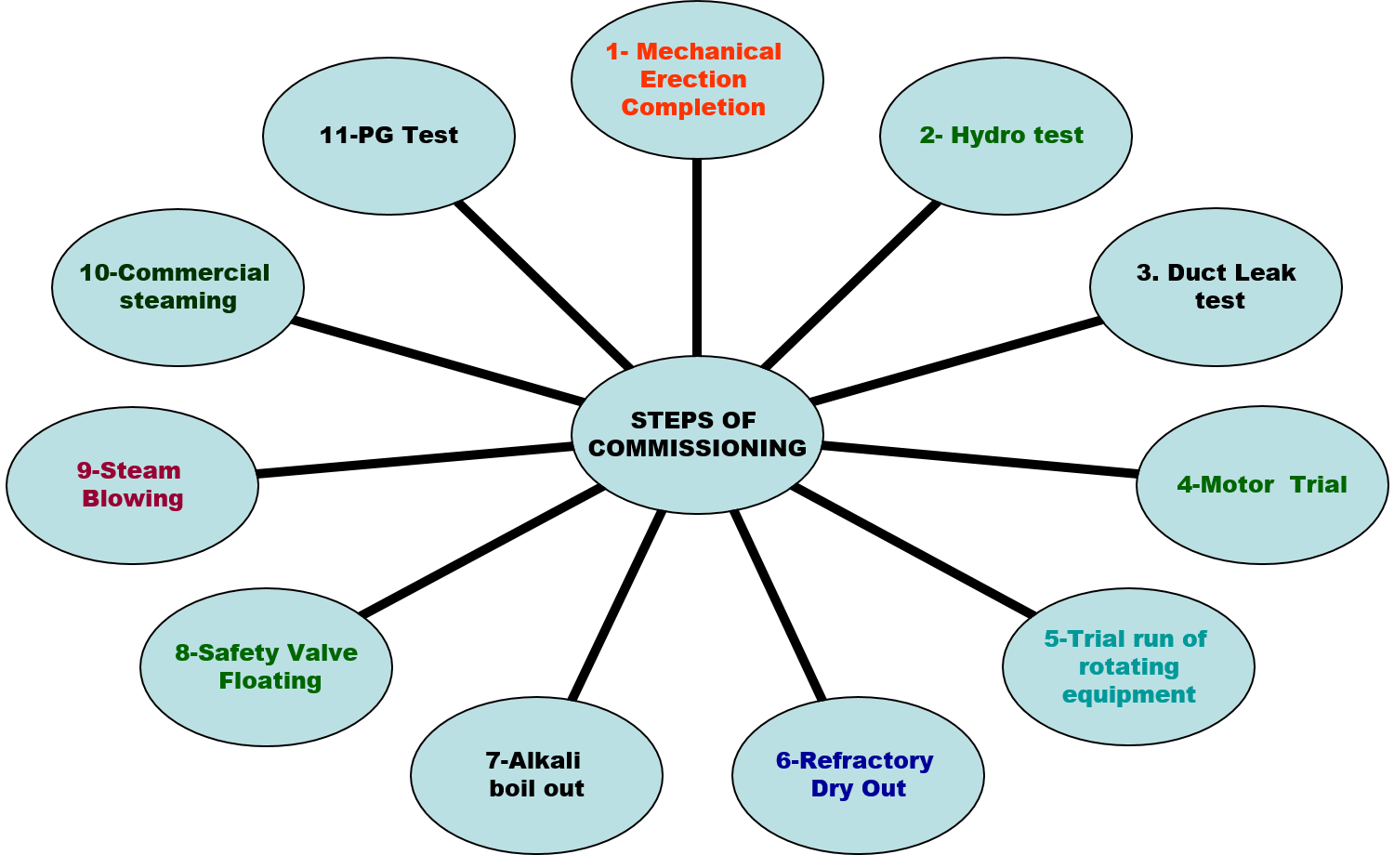
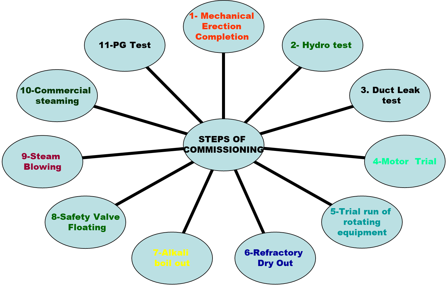
COMMISSIONING STAGES

WHY ??

To check the strength of all welding carried out and parts strength.

CARE TO BE TAKEN

• 

The boiler should be in cold condition. 

• Water used must be as near as possible to the boiler pressure parts temperature & the difference should not be more than 50 deg.            

• Maintain boiler water pH between 8.5 to 10.5 & hydrazine to approximately 150 ppm.

 Boiler must be hydro tested to 1.5 Times design pressure only for the first time after completion of the erection as per Regulation requirement. 

To ensure no Flue gas or Air leakage. This also reflects the completion of welding done on non pressure parts

IF NOT DONE:

Leakages during operation, loss in efficiency, a Load restriction

CARE TO BE TAKEN

•Take leak test of all ducting preferably with smoke.

• Take enough care for Air pre-heater Leak test

• Roof sealing to be carefully examined.

• Mark the leak area for attending it later. 

• Repair with good engineering practice

WHY

Controlled & Slow heating of refractory to remove moisture within it. Pressure parts are also heated up for the first time in a controlled manner

IF NOT DONE:

Cracking or separation of refractory may occur. Pressure parts may face thermal shocks

CARE TO BE TAKEN

In deciding initial heating temperature and its duration the following factors should be considered:

•Estimated moisture content of walls and refractory.

•Thickness of walls and refractory.

•The distance from the heat source.

•Strict follow-up of Drying curve

To descale and remove foreign materials from steam pipes leading to the turbine

IF NOT DONE THEN:

Damage to turbine blades from such material in the course of normal operation. 

PRINCIPLE 

STEAM BLOWING IS CARRIED OUT BY THE PUFFING METHOD TO: 

• Dislodge rust/scales from pipe work by thermal shocks. 

• High momentum of expanding steam in the pipe work purges out the loosened material. 

• It is required to create a higher momentum during steam blowing than possible during the operation of the unit. This applies to all steam piping leading to the turbine. 

• Care to be taken to terminate the discharge to a safer place

• Steam blowing completion criteria to be discussed & decided as per the application of steam

you can also check power plant commissioning

PRE-START CHECK

1.. Filling the boiler

  • If hot water has been used in the boiler, care should be exercised to feed slowly to avoid severe temperature strains. 
  • Make sure that all drains are closed before filling the boiler and that the unit is adequately vented during the filling procedure.
  • Fill until water is visible in the gauge glass. The steam drum vent should remain open during the filing operation and initial firing. 
  • It shall not be closed until all the air is vented from the unit and an appreciable quantity of steam is issuing, therefore. 
  • The unit may be considered free of air when the drum pressure reaches 2 kg per cm sq. 

2.. Super heater Drains/ Vents

•The superheater should be drained before lighting off through lines free from back pressure. 

•The superheater drain should be closed, and the superheater outlet vent must remain open to assure a flow of steam to protect the super-heater elements from overheating until the boiler has gone on the line and is carrying the load. 

•The vent valve may be throttled somewhat when the boiler pressure becomes sufficient to assure considerable flow through the superheater.

3.. Steam Gauge

The steam pressure gauges should be checked as soon as sufficient pressure is available. Blow out the connecting piping then check the action of the gauge needle to be sure that it is functioning. 

4.. Water Gauge

Check & Flush the water gauge if reqd

5.. Water Level 

•Water level is to be maintained at 50% level of the gauge glass. 

•During normal operation, the water level in the gauge glass should be observed periodically even though the boiler is equipped with a reliable feed water regulator or remote water level indicator.  

•Never shut off the feed water supply to a steaming boiler completely, not even for only a short period.

6.. Warming up Steam Lines

While the boiler is being brought up to pressure, provision should be made for gradually heating and adequately draining all cold steam piping. If the main steam line is cold, it is generally advisable to raise pressure on the line from the beginning by opening all valves.  

7.. Gas Temperature

The stack gas temperature will rise with an increasing load and fall with a decreasing load. If the gas temperature is above normal, look for

a. High excess air.

b. Fouled Firesides

c. Secondary combustion

8.. Steam Temperature 

The steam temperature varies with the load, raising as the load decreases. 

With constant load, abnormally high superheat steam temperature may be caused by :

a. Too high excess air.

 b. Too low feed water temperature

 c. Secondary Combustion

 d. Improper operation of automatic steam temperature indicating and control equipment. 

Superheater steam temperature below normal for the load may be caused by

a. Too low excess air

b. Too high feed water temperature

c. Excessive moisture carries over from the boiler

d.Excessive external deposits on superheater tubes

e.Improper operation of automatic steam temperature

indicating and controlling equipment

9.. Blow Downs 

The data on blowdowns should be recorded. Their frequency and duration are best determined from a chemical analysis of the boiler water.

•The use of the boiler bottom blow-off valves should be restricted to periods of moderate steaming rates and preferably a very low combustion rate.  

•The bottom blow down should always be used to free a boiler of sediment when the boiler is being cut out.  

•Never make the blow down long enough to lose sight of the water in the gauge glass. 

•Check the valves for leaks occasionally

A continuous blowdown line offers the best means for controlling the concentration of soluble salts in the boiler water, because, it maintains a relatively constant concentration 

10.. Soot Blowers 

The soot blower should be operated as often as necessary, to keep the external heating surfaces clean. Watching the gas temperature on the stack may indicate the need for blowing soot. 

Never use soot blowers on a cold boiler. 

It is good practice to blow soot just before taking the boiler out of service. 

Be sure that the combustion rate is high enough when blowing soot so that the fires are not extinguished.

Open the drain valve and let the steam blow freely long enough to heat the lines thoroughly before operating the soot blowers.  

The soot blower piping should be drained before each use to prevent damage to the soot blower elements by slugs of water.

TIPS FOR EFFICIENT OPERATION OF BOILER

FACTORS AFFECTING PERFORMANCE OF BOILER

  • Gas temperature leaving air heater
  • Excess air / O2 at Eco. outlet
  • Unburnt carbon in ash
  • Air leakage into furnace
  • Feed water and Boiler water quality
  • Deaerator in service
Categories
Blogs

DESIGN FEATURES OF  BOILER

 Boiler

General description of boiler

boiler is a device used to generate hot water or steam using chemical heat of fuel.

-fuels could be coal, oil, gas or any other biomass fuels like rice husk, bagasse, cane trash etc.  the mixed  composition of oil / gas fuel is also possible

-conversion of water to steam takes place by three heat addition

Troubleshooting of Boiler

Function of Drum:
-to produce water-free steam and steam-free water
-to remove steam bubble from water volume entering down comer to improve circulation
-mixing and distributing feed water
-adding chemicals
-facilitating blow down

drum internals:
-turbo separators
-primary drier
-secondary separator

Furnace:

-to provide enclosure for combustion of fuels

acts as evaporator by absorbing high temperature radiant heat by means of water cooled wall construction

-furnace design is governed by
*type of fuel
*allowable heat loadings
*burner arrangement

Boiler bank:
acts as evaporator by absorbing heat from flue gas by convective mode

necessary for low pressure boiler where large amount of latent heat is to be supplied to water to convert into steam

Superheaters :

Superheaters are designed to provide required degree superheat to steam.

they are designed to give designed performance with optimum material selection.

-superheater arrangement is finalised taking proper care of :

*spacing of tube
*steam velocity
*gas velocity
*temperature control 

Variable type desuperheater:

desuperheaters are provided for effectively controlling superheater outlet temperature.

type of desuperheater provided is water spray type.

provided between primary & secondary superheater

Economiser:
economiser is used to provide sensible heat to feed water
this is a convection heat transfer section located after boiler bank

  • designed considering factors like :
    • cold end corrosion
    • non steaming
    • erosion

Air heater:

air heaters are heat recovery section which absorbs the low temperature leaving boiler

they are located down stream of economiser

air heating helps combustion efficiency

-air heater help to improve boiler efficiency by optimally reducing gas temperature leaving boiler

Boiler auxiliaries :
fans :
for combustion of fuel air has to be supplied into the furnace and the gas generated in the furnace has to be thrown into stack continuously.
forced draft fan: air supplied for combustion through grate
secondary air fan: secondary air for spreader, & sa nozzle
induced draft fan : to evacuate the gases through chimney

Boiler feed pumps :
-boiler feed pumps are designed to give required feed water flow to boiler drum at desired pressure.
-they are multistage centrifugal pumps
-pumps are provided with auto recirculation valve for their low load projection

Soot blowers:

during the operation of boiler there is possibility of fouling or slag build up on heating surfaces of boiler depending on the fuel/ash characteristic

-such fouling will affect the performance of boiler like:
*boiler may not give required generation
*desired superheat temperature may not
be achieved
*draft loss will increase

-to take care of such eventuality, soot blowers are provided as on load cleaning device which are to be regularly used to over come slagging problem

-frequency of soot blowing shall be decided by studying the fuel characteristic

you can also check Troubleshooting of Boiler

Deaerator :
deaerators are provided to remove the dissolved oxygen in boiler feed water.

-oxygen in feed water is harm full for pressure part as they cause corrosion and pitting of pressure parts.

boiler shall never be operated for long time with deaerator out of service.

feed water temperature at the outlet of deaerator shall be 135°c.

Valve and Fittings:
-boiler is provided the valves for :
*controlling and regulating
steam/water flow
*isolating the lines
*prevent excess pressure build up
*to prevent back flow of fluid into
upstream side
valves plays vital roll in fluid
flow control and are to be maintained in good condition to get good availability of plant.

      TIPS FOR EFFICIENT OPERATION OF THE BOILER:

–Operation of the boiler with higher excess air than recommended means, higher dry gas loss and lower efficiency and higher power consumption.  Hence, it recommended to operate the  boiler at indicated values.

–Keep the gas temperature leaving closer to predicted value indicated.  Higher the gas temperature, lower would be the efficiency.

–Adjust the secondary air to get lower unburnt in ash.  Reduction in unburnt will improve the boiler efficiency.

–Prevent any leakage in furnace, ducting etc.  Ingress of air into the furnace will reduce efficiency and increase power consumption.

Always ensure minimum 30% MCR flow through superheater   

we also supply Boiler spare parts you can check that on our website

Categories
Blogs

TUBE FAILURES & TESTING EQUIPMENT

•TOPIC COVERS IN TUBE FAILURES AND TESTING

•VARIOUS INSPECTION TESTS, INCLUDING THE LATEST EQUIPMENT

•HOW TO HANDLE A PRESSURE PART FAILURE

•VARIOUS TYPES OF TUBES FAILURES, CAUSES & REMEDIES

Methods for inspection

  • Visual inspection                          
  • Thickness measurement               
  • DPT/MPT/UT   
  • NDT Test Selection      
  • Modern testing equipment  

TYPES OF TESTINGS FOR TUBE FAILURES

TESTING CLASSIFICATION

MOST POWERFUL INSPECTION TOOL

THUS VISUAL INSPECTION IS THE MASTER OF ALL TESTING

•DESTRUCTIVE

–TENSILE TEST

–COMPRESSION TEST

–BEND TEST

–IMPACT TEST

–MICRO/MACRO ANALYSIS

•NON-DESTRUCTIVE

–RADIOGRAPHY

–ULTRASONIC TESTING

–MAGNETIC PARTICLE TESTING

–DYE PENETRANT TESTING

–ELECTROMAGNETIC TESTING

–LEAK TESTING

–VISUAL TESTING

–RFID

–LFET

–IRIS

Types of tube failures

types of failure in tube

WHY PRE-HEATING OF BASE METAL?

• Pre-heat removes moisture content from base metal which can lead to poor welding quality.

•Distortion of base metal due to internal stresses developed during welding.

•Reduces hardness of weld metal 

•Control cooling rate to avoid cracking 

WHY BAKE LOW HYDROGEN ELECTRODES?

•Visible external porosity in addition to internal porosity.

•Moisture can cause slag removal difficult, a rough weld surface and cracking  

WHY CALIBRATION?

calibration

•To ensure proper working of instrument/equipment 

•Improper working of the baking oven can result in over/ under heating of the electrode 

•Improper working of welding equipment can lead to wrong operation characteristics of m/c resulting in welding defects

•Improper working of measuring instrument can lead to failure during assembly

FIBEROSCOPY/ VIDEOS COPY

Components  – 

Accessible internal surface of Tubes & Header

Visual inspection – Photographs of the inspected object taken

Fiberscope carried out where :

-Specimen may not be removed

 because it would weaken or 

 otherwise, render it useless for

 service.

-Part or structure too large to 

 bring to laboratory

-Object inaccessible

OXIDE SCALE MEASUREMENT

•Tube Temperatures > 900o F

•Failure prone to Creep Fatigue

•Oxide Scale formed (Fe2O3)

•Metal temperature increase 1-2o F increases creep damage

INSITU METALLOGRAPHY

Field surface Replication is a process that permits obtaining an image of a component surface with sufficient retention of fine structure to allow laboratory examination & evaluation without having to cut out a portion of the component. The assessment of grain size and precipitate spacing using both optical & electron microscopy can establish the presence of microstructural damage or changes and assist in understanding service conditions.

HOW TO HANDLE PRESSURE PARTS FAILURE

•Consider Pressure Parts failure as a serious lapse from either designer, erector, commissioning engineer or O & M staff.

•Treat it as a crime, and FIR must be logged with utmost care.

•Shut the unit as early as possible to minimize further damage.

•Gather as much as information possible related to failure, that includes data before failure, at the time of failure and after the failure 

•Preserve the operating log sheet and DCS trends as early as possible

•Spend a minimum of 15-30 minutes inspecting & investigating the failure area without disturbing the evidence.

•Take a Photograph of the failed and surrounding area along with noting critical observation.

•Inspect the adjacent tube condition with the same zeal & attitude.

•Type of failure would more often suggest the cause.

•Cut down the failed tube of @ 500 mm length, keeping failed spot at the centre. Cut the tube preferably with a hack saw.

•Before cutting the sample, mark tube no., the direction of fluid flow, side facing flue gas flow

•Do not remove the internal deposit of the cut tube and cover both ends of the cut tube. 

•Try to preserve the external deposit too.

•If overheating symptoms are there, it is advisable to cut one more sample from the adjacent un-failed tube.

•Send the tube sample to IJT H.O with proper packing along with the Data format filled.

•Carry out thorough Physical, chemical and metallurgical analysis of both tubes.

•Carry out deposit analysis collected from failed tubes. Which will indicate the water chemistry condition.

•Based on the analysis, the root cause can be concluded.

•Ensure that all the corrective actions on the boiler are incorporated at the earliest opportunity.

You can also check troubleshooting of Boiler

Various types of TUBE FAILURES

•During Manufacturing 

•During Transportation

•During Erection

•During Operation / In-Service

•Idle period.

Any Pressure part can be grouped into two classes.

•Water Cooled Tubing or Headers

•Steam Cooled Tubing and Headers

The failure mechanism of these parts differs marginally.

Categories
Blogs

MAINTENANCE & CHECKS FOR POWER PLANT

TOPICS COVERED :

  1. RECAP OF BOILER BASIC
  2. REQUIREMENT FOR INSPECTION 
  3. PART WISE CHECKLIST

RECAP…. Basics

Enclosed Pressure Vessel

The heat generated by the Combustion of Fuel is transferred to water to become steam Process: Evaporation.

Steam volume increases to 1,600 times that of water and produces tremendous force Boilers are hazardous equipment. Care is a must to avoid explosion.

Evaporation VS Boiling

 Normal evaporation is a surface phenomenon – since the vapor pressure is low and the pressure inside the liquid is equal to atmospheric pressure plus the liquid pressure, bubbles of water vapor cannot form. 

 But at the boiling point, the saturated vapor pressure equals atmospheric pressure, bubbles form, and the vaporization becomes a volume phenomenon. 

 INSPECTION & MAINTENACE

MOST POWERFUL INSPECTION TOOL

EYES are most valuable; take care of your eyes

THUS VISUAL INSPECTION IS THE MASTER OF ALL TESTING

Before starting any inspection, make sure that you should be equipped with.

• Safety Dress ( Boiler suit, Helmet, Eye Goggle, Safety Shoes, Knee pad, Safety Belt)

• A Power full torch

• A Scale and measuring Tape

• A pen with a small writing pad

• A marker and Chalk

• A Camera with proper holding arrangement

•Availability of drawing/relevant information of parts to be inspected

Boiler spare Parts & ash in a cooled condition

•Sufficient Illumination and proper scaffolding.

•Electrical connection removed

•Boiler isolated from another system

 •At least one semi-skilled labor for accompanying during the inspection

FURNACE

  • Check furnace water wall tube for any abnormal external scale or soot deposit. 
  • Try to find out the cause and analyze this deposit wrt fuel feeding, combustion, SA air nozzle location, etc.
  • If the deposition appears to be abnormal, it is advisable to have an analysis of this deposit. 
  • Analysis of same shall also provide the characteristics of fuel and its combustion-related properties.
  • Carry out thorough visual inspection of water wall tubes for swelling or thinning. 
  • Try to inspect the tubes viewing from bottom to top with the help of a torch light. This type of nonconventional inspection will highlight the swelling spots.
  • For thickness reduction (either through corrosion or erosion mechanism), always inspect the areas near fuel feeding and 

Secondary Air Nozzle insertion location into a furnace.

  • Carry out Thickness gauging from a reliable thickness meter at the predetermined spot to have a record of the same and to have a comparison at a later date for monitoring the thickness  

Reduction, if any.

  • Check and take corrective action for Fuel Spreader parts projected inside the furnace for wear and tear. Overheating and distortion of such items can be ruled out.
  •  Any welding done directly with the tubes for supporting or refractory holding purposes may require Dye Penetrant testing. This testing will be able to detect crack development. 
  •  Check the tightness of the buck-stay bolt

Operation And Maintenance Of Power Plant

 BOILER BANK

  • A boiler bank is an area that can not be inspected as a whole due to constraints in approach. Hence many areas which are prone to damage (erosion) can not be spotted easily. However, it is a must to inspect all the tubes in the areas of flue gas turn. Generally, manholes are provided at these locations.
  • Check the thickness of tubes sideways (3 & 6 O ‘clock position) at these locations.
  • Check the condition and Integrity of baffles provided for Flue gas turns. Any by-passing of flue gas from the designed flue gas path shall erode the tubes locally at a high rate; hence sufficient care needs to be given while inspecting these areas.
  • One may also take the help of modern instrumentation like Fibroscopy, RFET, LFET, or IRIS for inspecting the same.
  • Water drum top surface in boiler bank zone shall also be inspected, specifically if ash contains corrosive elements. 
  • We also advise checking randomly selected tubes by hands/fingers through steam or water drum at expanded portion for any abnormality.
  • Do not forget to inspect tubes in the vicinity of soot blowers.

SUPERHEATERS

  • Check tubes visually for a specific soot deposition pattern. 

  Remember, any particular pattern of soot deposition on super 

  hater coils, both vertically as well as horizontally, shall reflect 

  the combustion and flue gas pattern.

  • Check superheater tubes for any overheating or thinning symptoms. Although Thickness gauging can reflect the eroded portion, for overheating /swelling damage, it is useful to make a Gauge equivalent to the OD of the tubes and then check. This is a fast and helpful way to detect the 

 Swelling, if any.

  • Check the gap between the bottom bend of the superheater coil and the Gooseneck tube. Record it and cross-check it with the specified gap. Any abnormality in this shall reflect the expansion, supporting related problems exclusively for that loop.
  • Check specifically the superheater sealing area for any rubbing or gaps at the roof intersection point. The gap observed in this area shall cause flue gas leakage during operation, and rubbing may lead to failure at a later date.
  • The pitching of the coil and supporting arrangement need to be seen and recorded for comparison at a later date.
  • It is advisable to take a photograph of superheater coils in position prior to boiler light. This will help in comparing the misalignment at a later stage. 
  • ECONOMIZERS
  • AIR HEATERS
  • STEAM DRUM

OTHER INSPECTION AREAS

  •  Check the condition of supports (specifically hanger supports).
  •    Inspect ID fan impeller, suction cone, and related ducting 

For any abnormal wear and tear.

  • Have a look at expansion joints provided in the main flue gas 

     Passage. There is every possibility of leakage/ingress 

     through the gaps.

  • Do not forget to attend to the areas of leakages that were 

     identified during the operation of the boiler

  • Check the condition of the refiring grit nozzle & its location
  • Inspect Stoker from Catenary for any abnormal wear of Grate bar and damage of Supporting beam, chain, and other parts.
  • Check condition, Integrity, and ash deposition on guide baffle plate provided in various ducts.
  • Check Ducts & Hoppers for any distortion, overheating, or refractory damage ( if provided)
  • Check & Mark the leakage area from the furnace and ducts.
  • Check the condition of Grit Interceptor pipes for erosion or damage
  • Check Deaerator Spray nozzles, condenser & Tray supporting arrangement 
Categories
home page

Who We Are?

“SKV Energy” Power Plant Consultants In India is a Team of Power Plant Professionals having good experience in Commissioning, Operation and Maintenance, Trouble Shooting of boiler, Capacity Enhancement, Relocation, Energy Audit, and various other activities related to Power Plants. We are also known as the Power plant equipment suppliers 

We deliver cost-effective, reliable Operation And Maintenance services and high-quality solutions & services of strategic value to our clients. We are one of the best Consultants for Power plants In India.  

We have made all efforts To be the most admired and responsible Operation And Maintenance Of a Power Plant service company, delivering sustainable value to be a top Power Plant Operations Company In India while delivering services that consistently meet international standards and standard operating procedures. To Possess a team of Qualified and skilled Professionals to have the in-house capability for Power plant commissioning, Operation and Maintenance, Troubleshooting for Boilers.

Categories
home page

What we do

  • Power Plant Commissioning 
  • Operation and Maintenance of Power Plant 
  • Troubleshooting of Boiler
  • Power plant Consultants
  • Power plant equipment supplier
  • Performance & Efficiency Improvement
  • Shutdown maintenance services
  • Project management services

Categories
home page

We specialize in

  • Commissioning of AFBC, CFBC, PF, WHRB, Travelling Grate, Pulsating Grate boilers, Dumping Grate boilers.
  • Operation And Maintenance Of Power Plant
  • We improve performance, efficiency, and availability improvement of power plants.
  • Improve the performance of the power plant and reduce the Operation And Maintenance Cost Of the Power Plant.
  • Power plant equipment suppliers like Boiler spare parts, Ash handling system spares, Fuel handing, Equipment parts for Other BOP equipment & general hardware items.

Why SKV is the best Power Plant Consultants In India?

  • O&M Services with optimized Manpower.
  • We Ensure Higher plant availability.
  • We Ensure the implementation of O&M management systems.
  • We Ensure our company is top in the List of Power plant consultants in India
  • Best Shutdown Maintenance Services for Power Plant.

Categories
Uncategorized

Our Achievements

  • M/s ACC Limited –Bonus received for plant availability 99.5%(The year 2014 -2017)
  • M/s Ambuja Cement-Obtained appreciation certificate for timely commissioning
  • L&T appreciation certificate for timely commissioning
  • M/s UPL Gujrat – Obtained Plant availability of more than 97%
  • High employee retention Achievements
Categories
home page

Our mission

  • Ensuring customer satisfaction, trust, and integrity by delivering quality power plant equipment, Boiler spare parts, and power plant Operation And Maintenance services conforming to industry best practices.
  • To be a high-performance, sought-after Professional Organization that exceeds all customer expectations.
  • Provide an enriching, fulfilling, and rewarding environment for its employees.
  • Remain a recognized leader in the List Power Plant Consultants In India with professional engineering technology, engineering services, and solutions to the industry.
  • We Deliver cost-effective, ethical, reliable, and high-quality solutions of strategic value while sustaining a challenging and rewarding work environment for our greatest asset, our employees.
  • Cost-effective services Performance improvements through innovation & cross-learning.